

This article is copied as is from makeuseof.com:
While a single Arduino can accomplish many tasks, some projects may call for the use of more than one board to handle different functionalities. So, to enable data transfer between the two microcontrollers, a communication protocol such as CAN, SPI, I2C, or UART must be set up.
In this guide, we will cover the basics of how I2C works, the hardware connections, and the software implementation needed to set up two Arduino boards as I2C master and slave devices.
What Is I2C?
Inter-Integrated Circuit (I2C) is a widely used communication protocol in embedded systems and microcontrollers to enable data transfer between electronic devices. Unlike SPI (Serial Peripheral Interface), I2C allows you to connect more than one master device to a bus with single or multiple slave devices. It was first used by Philips and is also known as the Two Wire Interface (TWI) communication protocol.
How Does I2C Communication Work?
I2C uses two bidirectional lines: Serial Data (SDA) and Serial Clock (SCL) to transfer data and synchronize communication between devices. Each device connected to the I2C bus has a unique address that identifies it during communication. The I2C protocol allows multiple devices to share the same bus, and each device can act as a master or a slave.
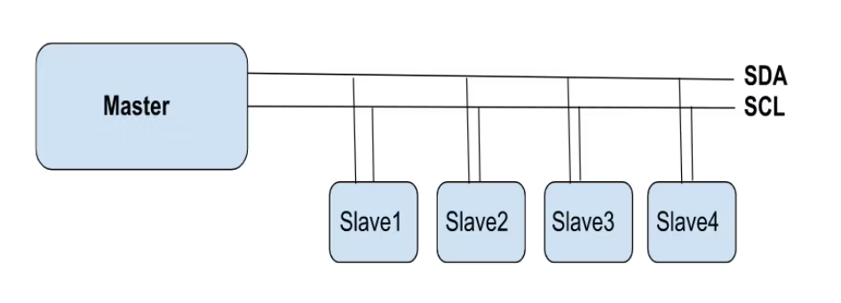
Communication is initiated by the master device, and incorrect addressing of slave devices can cause errors in transfer. Check out our in-depth guide on how UART, SPI, and I2C serial communications work to give you some context.
A major advantage of I2C communication worth noting is the flexibility that it offers when it comes to power management. Devices that operate at different voltage levels can still communicate effectively with the help of voltage shifters. This means that devices operating at 3.3V need voltage shifters to connect to a 5V I2C bus.
The Wire Library
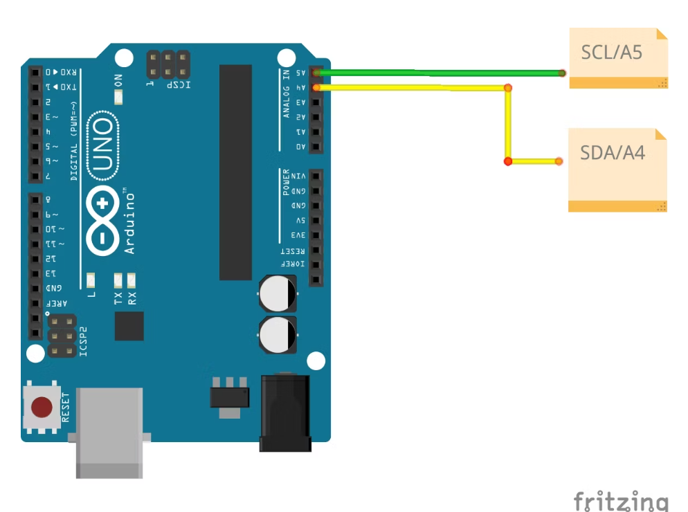
The Wire library is a built-in Arduino library that provides functions to communicate over I2C. It uses two pins—SDA and SCL—on the Arduino board for I2C communication.
I2C pins on the Arduino Uno:
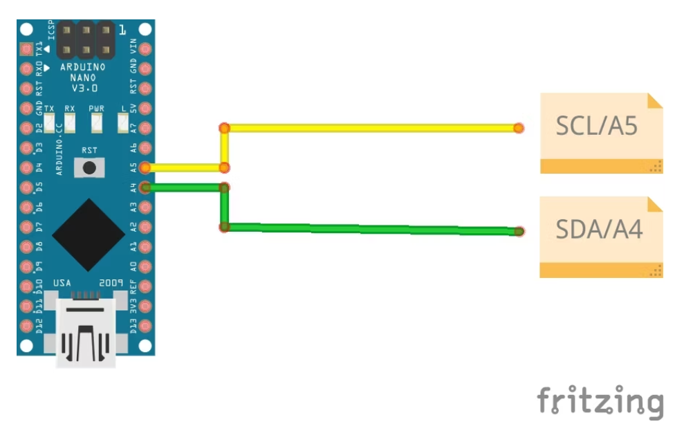
Arduino Nano I2C pins:
To use the library, you must include the Wire.h header file at the beginning of your Arduino sketch.
#
The Wire library provides functions to initiate communication with an I2C device, send data, and receive data. Some important functions you should know include:
- Wire.begin(): used to join the I2C bus and initiate communication.
- Wire.beginTransmission(): used to specify the slave address and begin a transmission.
- Wire.write(): used to send data to the I2C device.
- Wire.endTransmission(): used to end the transmission and check for errors.
- Wire.requestFrom(): used to request data from the I2C device.
- Wire.available(): used to check if data is available to read from the I2C device.
- Wire.read(): used to read data from the I2C device.
Use the Wire.beginTransmission() function to set the address of the sensor, which is inserted as an argument. For example, if the sensor's address is 0x68, you would use:
Wire.beginTransmission(0x68);
Arduino I2C Hardware Setup
To connect two Arduino boards using I2C, you will need the following hardware components:
- Two Arduino boards (master and slave)
- Breadboard
- Jumper wires
- Two 4.7kΩ pull-up resistors
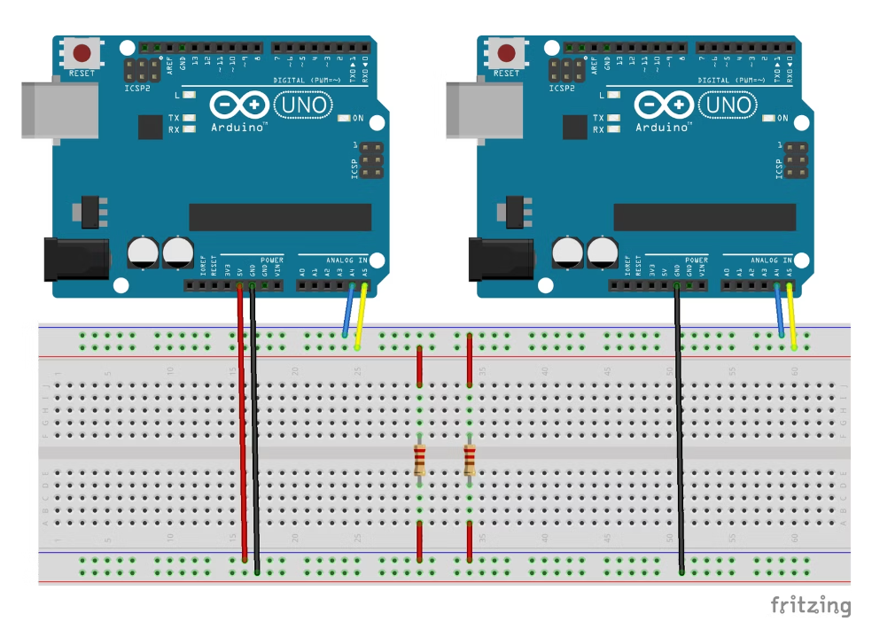
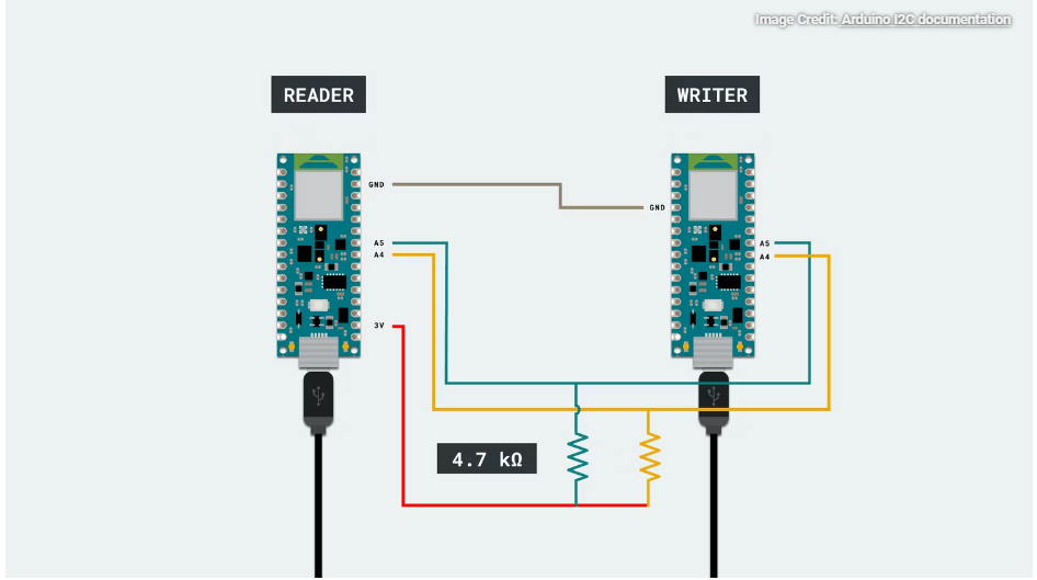
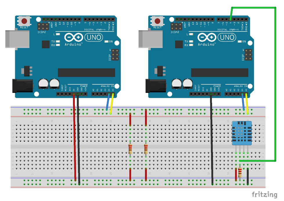
Connect the SDA and SCL pins of both Arduino boards to a breadboard. Connect the pull-up resistors between the SDA and SCL pins and the 5V power rail on the breadboard. Finally, connect the two breadboards together using jumper wires.
Arduino Uno circuit
Arduino Nano Circuit
Setting Up the Arduino Boards as I2C Master and Slave Devices
Use the Wire.requestFrom() function to specify the address of the slave device that we want to communicate with. Then use the Wire.read() function to get data from the slave device.
Master device code:
#include <Wire.h>
void setup() {
Wire.begin(); // join i2c bus
Serial.begin(9600); // start serial for output
}
void receiveData() {
int address = 8;
int bytesToRead = 6;
Wire.requestFrom(address, bytesToRead);
while (Wire.available()) {
char data = Wire.read();
Serial.print(data);
}
delay(500);
}
void loop() {
receiveData();
}
The Wire.onReceive() function is used to specify what to do when the slave receives data from the master device. In the above code, the Wire.available() function checks if data is available, and the Wire.read() function reads the data sent by the master device.
Slave device code:
#include <Wire.h>
void setup() {
Wire.begin(8); // join the I2C bus with address 8
Wire.onReceive(receiveEvent); // call receiveEvent when data is received
}
void loop() {
delay(100);
}
void receiveEvent(int bytes) {
Wire.write("hello "); // respond with message of 6 bytes as expected by master
}
Sending and Receiving Data Using I2C
In this example, let’s read the temperature from a DHT11 temperature sensor interfaced with the slave Arduino and print it on the serial monitor of the master Arduino.
Let's modify the code we wrote earlier to include the temperature measurement which we will then send to the master board over the I2C bus. The master board can then read the value we sent, then display it on the serial monitor.
Master device code:
#include <Wire.h>
void setup() {
Wire.begin();
Serial.begin(9600);
Serial.println("Master Initialized!");
}
void loop() {
Wire.requestFrom(8, 1); // Request temperature data from slave
if (Wire.available()) {
byte temperature = Wire.read(); // Read temperature data from slave
Serial.print("Temperature: ");
Serial.print(temperature);
Serial.println(" °C");
}
delay(2000); // Wait for 2 seconds before requesting temperature again
}Slave device code:
#include <Wire.h>
#include <DHT.h>

#define DHTPIN 4 // Pin connected to DHT sensor
#define DHTTYPE DHT11 // DHT sensor type
DHT dht(DHTPIN, DHTTYPE);
byte temperature;

void setup() {
Wire.begin(8); // Slave address is 8
Wire.onRequest(requestEvent);
dht.begin();
}

void loop() {
delay(2000); // Wait for 2 seconds for DHT to stabilize
temperature = dht.readTemperature(); // Read temperature from DHT sensor
}

void requestEvent() {
Wire.write(temperature); // Send temperature data to master
}
You can customize this code to suit whichever sensors you may have in your project, or even display the sensor values on a display module to make your own room thermometer and humidity meter.
Slave Addressing With I2C on Arduino
To read values from components added to an I2C bus in such a project, it is important that you include the correct slave address when coding. Luckily, Arduino offers a scanner library that simplifies the process of identifying slave addresses, eliminating the need to sift through lengthy sensor data sheets and confusing online documentation.
Use the following code to identify any slave device’s address present on the I2C bus.
#include <Wire.h> // Include the Wire library for I2C communication

void setup() {
Wire.begin(); // Initialize the I2C communication
Serial.begin(9600); // Initialize the serial communication with a baud rate of 9600
while (!Serial); // Wait for the serial connection to establish
Serial.println("\nI2C Scanner"); // Print a message indicating the start of I2C scanning
}

void loop() {
byte error, address; // Declare variables to store errors and device addresses
int nDevices; // Declare a variable to store the number of devices found

Serial.println("Scanning..."); // Print a message indicating the start of I2C scanning

nDevices = 0; // Set the number of devices found to 0
for (address = 1; address < 127; address++) { // Iterate over all possible I2C addresses
Wire.beginTransmission(address); // Start a transmission to the current address
error = Wire.endTransmission(); // End the transmission and store any errors

if (error == 0) { // If no errors were found
Serial.print("I2C device found at address 0x"); // Print a message indicating a device was found
if (address < 16) Serial.print("0"); // If the address is less than 16, add a leading 0 for formatting purposes
Serial.print(address, HEX); // Print the address in hexadecimal format
Serial.println(" !"); // Print a message indicating a device was found

nDevices++; // Increment the number of devices found
}
else if (error == 4) { // If an error was found
Serial.print("Unknown error at address 0x"); // Print a message indicating an error was found
if (address < 16) Serial.print("0"); // If the address is less than 16, add a leading 0 for formatting purposes
Serial.println(address, HEX); // Print the address in hexadecimal format
}
}
if (nDevices == 0) { // If no devices were found
Serial.println("No I2C devices found\n"); // Print a message indicating no devices were found
}
else { // If devices were found
Serial.println("done\n"); // Print a message indicating the end of I2C scanning
}
delay(5000); // Delay for 5 seconds before starting the next scan
}
Expand Your Project Today
Interfacing two Arduino boards using the I2C communication protocol offers a flexible and efficient way of achieving complex tasks that cannot be handled by a single board. With the help of the Wire library, communication between the two boards using I2C is made easy, allowing you to add more components to your project.