


Creating a mobile Bluetooth-controlled Mecanum wheels robot car is an exciting project that combines mechanics, electronics, and programming. In this comprehensive guide, we’ll walk you through the process of building a versatile robot car with 4 Mecanum wheels, a 4-wheel chassis kit, an L298N motor driver, an HC-05 Bluetooth module, two 18650 Li-Ion batteries for power, and an Arduino Uno for control. This project is not only fun but also educational, making it suitable for beginners and robotics enthusiasts. Let’s dive in!
You can watch the following video or read the written tutorial below.
Materials Needed
- 4 Mecanum wheels
- 4-wheel chassis kit with DC motors
- 2 x L298N motor driver module
- HC-05 Bluetooth module
- Two 18650 Li-Ion batteries and a battery holder
- Jumper wires
- 12V DC Jack (Male , Female)
- Screwdriver and assorted screws
- Solder iron
- Glue gun
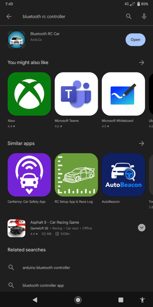
- Mobile device with the Bluetooth RC Control app installed


Step 1: Assemble the Chassis
Start by assembling the 4-wheel chassis kit following the manufacturer’s instructions. This typically involves attaching the wheels, motors, and the chassis base. Ensure that your robot car can move freely, and the wheels are securely attached.

Step 2: Mount the Mecanum Wheels
Mount the 4 Mecanum wheels on the robot’s chassis. Make sure they are correctly aligned so that they can provide omnidirectional movement. Each wheel should be oriented diagonally to the chassis, creating an “X” pattern.


Step 3: Assemble the Parts
Install the parts so that the weight is equal on all four wheels.


Mecanum Wheels Robot Car Circuit Diagram
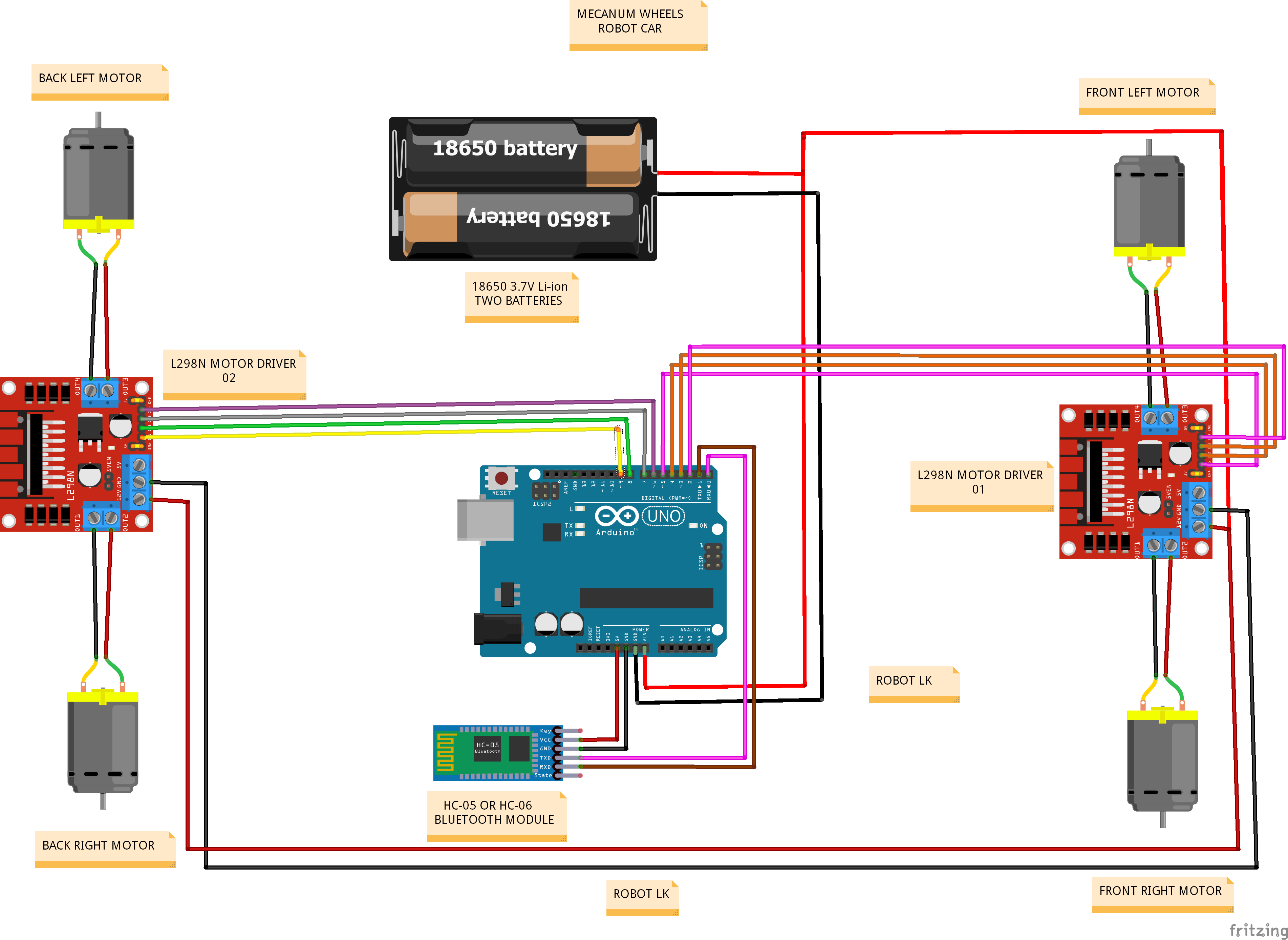
Step 4: Connect the Motors to the L298N Driver
The L298N motor driver module will allow you to control the speed and direction of the robot’s motors. Connect the motor wires to the motor driver as follows:


- Connect the wires from the Front Left motor Red wire to the “OUT3” terminals on the First motor driver.
- Connect the wires from the Front Left motor Black wire to the “OUT4” terminals on the First motor driver.
- Connect the wires from the Front Right motor Red wire to the “OUT2” terminals on the First motor driver.
- Connect the wires from the Front Right motor Black wire to the “OUT1” terminals on the First motor driver.
- Connect the wires from the Back Left motor Red wire to the “OUT3” terminals on the Second motor driver.
- Connect the wires from the Back Left motor Black wire to the “OUT4” terminals on the Second motor driver.
- Connect the wires from the Back Right motor Red wire to the “OUT2” terminals on the Second motor driver.
- Connect the wires from the Back Right motor Black wire to the “OUT1” terminals on the Second motor driver.
Step 5: Connect the power to the L298N Driver


- Connect the wires from the Battery holder Red wire to the 12V in terminals on the First motor driver and Second motor driver.
- Connect the wires from the Battery holder Black wire to the GND terminals on the First motor driver and Second motor driver.
Step 6: Connect the power to the Arduino UNO

Provide power to the Arduino UNO by connecting the positive (VIN ) and negative (GND) terminals of the battery holder or power supply to the “+” and “-” terminals on the motor driver.
Step 7: Connect the Arduino UNO to the L298N Drivers
The L298N motor driver module allows you to control the speed and direction of the robot’s motors. Connect the Arduino to the motor driver as follows:

First Motor Driver
- IN 1 to digital pin D5 on Arduino.
- IN 2 to digital pin D4 on Arduino.
- IN 3 to digital pin D3 on Arduino
- IN 4 to digital pin D2 on Arduino.
Second Motor Driver
- IN 1 to digital pin D9 on Arduino.
- IN 2 to digital pin D8 on Arduino.
- IN 3 to digital pin D7 on Arduino
- IN 4 to digital pin D6 on Arduino.
Step 8: Wire Up the HC-05 Bluetooth Module
Connect the HC-05 Bluetooth module to the Arduino Uno as follows:

- Connect VCC to 5V on the Arduino.
- Connect GND to GND on the Arduino.
- Connect TXD to RX (pin 0) on the Arduino.
- Connect RXD to TX (pin 1) on the Arduino.
Step 9: Upload the Arduino Sketch
It’s time to program your Arduino Uno. You’ll need to upload a sketch (code) that reads commands from the Bluetooth module and controls the motors accordingly.
//MECANUM WHEELS ROBOT
//ROBOT LK

#define IN_11  2        // L298N #1 in 4 motor Front Right
#define IN_12  3        // L298N #1 in 3 motor Front Right
#define IN_13  4        // L298N #1 in 2 motor Front Left
#define IN_14  5        // L298N #1 in 1 motor Front Left

#define IN_21  6        // L298N #2 in 4 motor Back Left
#define IN_22  7       // L298N #2 in 3 motor Back Left
#define IN_23  8       // L298N #2 in 2 motor Back Right
#define IN_24  9      // L298N #2 in 1 motor Back Right

//ROBOT LK


int command;             //Int to store app command state.
boolean state = 1;


void stopRobot() {
  digitalWrite(IN_11, LOW);
  digitalWrite(IN_12, LOW);

  digitalWrite(IN_13, LOW);
  digitalWrite(IN_14, LOW);

  digitalWrite(IN_24, LOW);
  digitalWrite(IN_23, LOW);

  digitalWrite(IN_22, LOW);
  digitalWrite(IN_21, LOW);

}
void back() {
  digitalWrite(IN_11, LOW);
  digitalWrite(IN_12, HIGH);

  digitalWrite(IN_13, LOW);
  digitalWrite(IN_14, HIGH);

  digitalWrite(IN_24, HIGH);
  digitalWrite(IN_23, LOW);

  digitalWrite(IN_22, HIGH);
  digitalWrite(IN_21, LOW);

}
void forward () {
  digitalWrite(IN_11, HIGH);
  digitalWrite(IN_12, LOW);

  digitalWrite(IN_13, HIGH);
  digitalWrite(IN_14, LOW);

  digitalWrite(IN_24, LOW);
  digitalWrite(IN_23, HIGH);

  digitalWrite(IN_22, LOW);
  digitalWrite(IN_21, HIGH);

}
void left() {
  digitalWrite(IN_11, HIGH);
  digitalWrite(IN_12, LOW);

  digitalWrite(IN_13, LOW);
  digitalWrite(IN_14, HIGH);

  digitalWrite(IN_24, LOW);
  digitalWrite(IN_23, HIGH);

  digitalWrite(IN_22, HIGH);
  digitalWrite(IN_21, LOW);

}
void right() {
  digitalWrite(IN_11, LOW);
  digitalWrite(IN_12, HIGH);

  digitalWrite(IN_13, HIGH);
  digitalWrite(IN_14, LOW);

  digitalWrite(IN_24, HIGH);
  digitalWrite(IN_23, LOW);

  digitalWrite(IN_22, LOW);
  digitalWrite(IN_21, HIGH);

}
void superleft () {
  digitalWrite(IN_11, LOW);
  digitalWrite(IN_12, HIGH);

  digitalWrite(IN_13, HIGH);
  digitalWrite(IN_14, LOW);

  digitalWrite(IN_24, LOW);
  digitalWrite(IN_23, HIGH);

  digitalWrite(IN_22, HIGH);
  digitalWrite(IN_21, LOW);

}
void superright () {
  digitalWrite(IN_11, HIGH);
  digitalWrite(IN_12, LOW);

  digitalWrite(IN_13, LOW);
  digitalWrite(IN_14, HIGH);

  digitalWrite(IN_24, HIGH);
  digitalWrite(IN_23, LOW);

  digitalWrite(IN_22, LOW);
  digitalWrite(IN_21, HIGH);

}
void forwardright () {
  digitalWrite(IN_11, LOW);
  digitalWrite(IN_12, LOW);

  digitalWrite(IN_13, HIGH);
  digitalWrite(IN_14, LOW);

  digitalWrite(IN_24, LOW);
  digitalWrite(IN_23, LOW);

  digitalWrite(IN_22, LOW);
  digitalWrite(IN_21, HIGH);

}
void forwardleft () {
  digitalWrite(IN_11, HIGH);
  digitalWrite(IN_12, LOW);

  digitalWrite(IN_13, LOW);
  digitalWrite(IN_14, LOW);

  digitalWrite(IN_24, LOW);
  digitalWrite(IN_23, HIGH);

  digitalWrite(IN_22, LOW);
  digitalWrite(IN_21, LOW);

}
void backleft () {
  digitalWrite(IN_11, LOW);
  digitalWrite(IN_12, HIGH);

  digitalWrite(IN_13, LOW);
  digitalWrite(IN_14, LOW);

  digitalWrite(IN_24, HIGH);
  digitalWrite(IN_23, LOW);

  digitalWrite(IN_22, LOW);
  digitalWrite(IN_21, LOW);

}
void backright () {
  digitalWrite(IN_11, LOW);
  digitalWrite(IN_12, LOW);

  digitalWrite(IN_13, LOW);
  digitalWrite(IN_14, HIGH);

  digitalWrite(IN_24, LOW);
  digitalWrite(IN_23, LOW);

  digitalWrite(IN_22, HIGH);
  digitalWrite(IN_21, LOW);

}
void setup() {
  Serial.begin (9600);

  pinMode(IN_11, OUTPUT);
  pinMode(IN_12, OUTPUT);
  pinMode(IN_13, OUTPUT);
  pinMode(IN_14, OUTPUT);

  pinMode(IN_21, OUTPUT);
  pinMode(IN_22, OUTPUT);
  pinMode(IN_23, OUTPUT);
  pinMode(IN_24, OUTPUT);


}
//ROBOT LK

void loop() {
  if (Serial.available()) {
    command = Serial.read();
    if (command == 'X') {
      state = 1;
    } else if (command == 'x') {
      state = 0;
    }
    if (command == 'B') {
      back();
    } else if (command == 'F') {
      forward();
    } else if (command == 'R' && state == 1) {
      superright ();
    } else if (command == 'L' && state == 1) {
      superleft ();
    } else if (command == 'R' && state == 0) {
      right ();
    } else if (command == 'L' && state == 0) {
      left ();
    } else if (command == 'G') {
      forwardleft ();
    } else if (command == 'I') {
      forwardright ();
    } else if (command == 'H') {
      backright ();
    } else if (command == 'J') {
      backleft ();
    }  else {
      stopRobot();
    }
  }
}
//robot lkThis code allows the Arduino to receive commands from the Bluetooth module and control the motors for movement.
Step 10: Control Your Robot Car
Pair your mobile device with the HC-05 Bluetooth module and open the Bluetooth RC Control app. Connect to the module and start controlling your Mecanum wheels robot car wirelessly. The app’s interface will allow you to send commands to your robot car for forward, backward, left, right, Super left, Super right, forward left, forward right, backward left, backward right and stop movements.


forward, backward, left, right movements.

Super left, Super right, forward left, forward right, backward left, backward right movements.
Conclusion
By following this guide, you’ve successfully built a mobile Bluetooth-controlled robot car with Mecanum wheels. This project provides not only a fun experience but also an opportunity to learn about robotics, mechanics, and programming. You can further enhance your robot car by adding sensors, autonomous navigation capabilities, or additional features to make it even more versatile and interactive. Enjoy exploring the exciting world of robotics!